An overview of the instrument can be found here, this page details the design of the rotating front end.
Field Corrector
The first major component of MOONS is the field corrector, which ensures that the exit pupil of the VLT is almost concentric to the focal plane’s curvature. The corrector has the additional advantage that it reduces the radius of curvature of the focal plane, making the focal plane closer to a flat surface, which significantly simplifies the assembly of the units on the focal plate. The field corrector is comprised of plano-convex lens followed by a symmetrical biconcave element, as can be seen in the image below. As with nearly all the other transmissive elements in MOONS, these lenses are made of low OH Fused Silica (<10 ppm).

Focal Plate
All the Fiber Positioning Units (FPUs), the Acquisition Cameras (ACs) and the fiducials for the metrology cameras are mounted on one monolithic plate. All three of these elements use a common triangular mounting pattern that can be clearly seen in the picture below. The near 1 m diameter plate therefore has 1069 identical facets; the final system will have 20 ACs and 48 fiducials, leaving 1001 spaces for FPUs.

The black circles represent the Aquisition Cameras, the red circles the fiducials for the metrology system and the purple bars are the beta arms of the 1001 FPUs.
The chief ray is not perfectly perpendicular to the plate and consequently all 1069 facets have slightly different angles relative to the surface. The error on these facets forms a non-negligible component of the total tilt error allowed on the fiber, which is a critical requirement for the instrument.
The focal plane of the VLT lies only 114mm behind the back surface of the field corrector. Therefore it is not possible to view the positioners from within MOONS without retracting the focal plate away from the field corrector. In the science position the plate is driven against three machined hard stops that critically define the overall plate tilt relative to the optical axis. Note though, the exact lateral position is not critical as the ACs are used for the precise alignment of the plate on the sky.

The real machined focal plate, ready to be populated.
Fiber Positioning Units (FPUs)
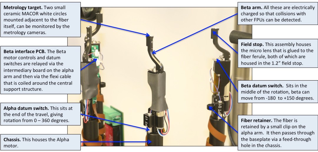
Arguably the most complex element of MOONS is the fiber positioning system, which consists of 1001 independent FPUs. Each FPU has two stepper motors, which drive an alpha and beta arm that act like an elbow and shoulder joint to give complete coverage over a small region of the focal plane. Due to the desire for excellent sky-subtraction the MOONS FPUs are able to reach the centre of their neighbouring FPU’s patrol field, thus increasing the density of field coverage.
One of the most challenging design aspects for the FPUs has been the tilt requirement. Each FPU must be aligned with the telescope’s chief ray, even when the arm is fully extended; failure to achieve this requirement would mean that the fiber will not see the full pupil of the telescope, leading to a variation in transmission for the fiber. The FPUs are being manufactured by the MPS group in Switzerland; by working closely with them and the motor manufacturers Faulhaber, we have been able to meet the remarkably tight tilt tolerance of the FPUs.
All this has been achieved whilst also trying to ensure that the effects of Focal Ratio Degradation (FRD) are minimized. Both stress testing of the fibers in free space and lifetime testing with the FPUs has been carried out to monitor whether the repeated twisting of the fibers has any impact on FRD, or indeed whether the interaction of the fiber with the mechanical structure of the FPU damages the fiber in any way. All testing has shown that the effects are minimal.
Metrology System
The metrology cameras monitor the precise positioning of the FPUs when the plate is retracted. They are capable of measuring the location of an FPU to <15 microns. There are 12 cameras mounted around the edge of the field corrector each of which can see a section of the field plate as can be seen in the image below. Due to the off-axis location of the cameras it would not be possible to view any light exiting the fibers even if they could be back-illuminated. Instead each FPU has a metrology target mounted on the Beta arm comprised of two circular discs made of the ceramic MACOR, which delivers a diffuse reflection that is invariant of the location of the light source.

Each green trapezium represents the field of view of one metrology camera on the focal plate. The red circles show fiducials used to give calibration of the exact plate scale and overlap between the cameras. As can be seen, all cameras can measure the central fiducial simultaneously.
The focal plate is illuminated by a set of lamps around the edge of the plate. The light reflected from the metrology targets is then identified using the astronomical software Source-Extractor, which allows quick filtering of the results to reject any scattered light artefacts.
Every camera can see 13 different fiducial markers. These are at fixed positions across the plate that will have been measured to very high precision during integration. Many of the fiducials and ~80% of the FPUs can be seen by multiple cameras, thus increasing the precision of the individual measurements and ensuring accurate measurements across the whole plate. The plate is also fitted with thirteen temperature sensors to allow any corrections for plate expansion/contraction to be made.
Calibration System
The MOONS calibration unit provides both flat fielding and wavelength calibration for all the fibers. Behind the field corrector are two sliding doors that can be closed to form a large screen that is visible to all the FPUs. This screen is coated in a Lambertian diffuser, which provides uniform reflectivity. Onto this surface the different lamps are projected.
To ensure excellent sky-subtraction it is critical that the relative transmission of all the fibers is known to better than 1% and to achieve this the spatial variation of the flux across the calibration screen must also be equally flat. Note though that this flatness is only required over the 30 mm scale-lengths viewed by each fiber, which greatly simplifies the flatness requirement. To achieve this level of flatness MOONS is using a spatially uniform light source. One of the beauties of this system is that flat fields can be taken for the FPUs once they are in their observing positions.
Acquisition Cameras
MOONS has 20 ACs distributed across the focal plane that are used for fine alignment of the instrument on sky. Each camera has a fov of 37×37”, although only the central 30” diameter is completely unvignetted. The cameras have very few elements and since they sit at the VLT’s focal plane, are extremely sensitive. It is expected that even a 21st magnitude object can be observed in under 30s to the required S/N to allow offset computation. The ACs are spaced at different radial distances so that by rotating the instrument effectively the whole fov of the VLT can be used. Detailed sky modelling suggests that there is >99% chance that the observer will be able to identify 3 stars that are brighter than 19th mag, even at high galactic latitudes.

A prototype Acquisition Camera mounted next to a prototype FPU. As can be seen, the Camera is much lower than the FPU, allowing the FPU to move over the top of it when the camera is not in use to ensure good field coverage.
